
Introduction: The Two Guardians of Relay Circuits
If you have been designing relay driver circuits for a while, you probably know the flyback diode that trusty component sitting across the relay coil, protecting your switching transistor from voltage spikes. You put it there, feel safe, and move on.
Then a more experienced engineer looks at your schematic and asks: "Where's your RC snubber?"
You think don't I already have the flyback diode? Why do I need both?
This is one of the most important questions in relay circuit design. And the answer reveals a beautiful truth about how electromagnetic components behave in the real world versus how we wish they behaved on paper. Let's go deep.
The Real Life Analogy: Water Pipe Analogy
Imagine you have a garden hose with water flowing through it at full pressure. You are watering your plants. Now someone suddenly slams the tap shut completely in one sharp motion.
What happens? The water that was rushing forward has momentum. It cannot stop instantly. It slams into the closed tap and creates a violent pressure shockwave back through the pipe this is called water hammer. It can rattle your pipes, crack joints, and even burst the tap itself.
This is exactly what happens electrically when you switch off a relay coil. The current flowing through the coil has momentum (inductance). When the transistor slams it off, the current cannot stop instantly. It creates a massive voltage spike your electrical "water hammer.
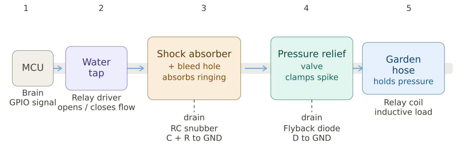
MCU is the smart timer controller on the wall. It just presses a button — no heavy lifting.
Relay driver is the motorised tap. It receives the button press and physically slams the water flow shut. That slam is the moment all trouble starts.
RC snubber is the air chamber + bleed hole on the pipe. The moment the tap slams, water vibrates back and forth violently. The air pocket soaks up that oscillation and the bleed hole quietly drains the energy away to ground.
Flyback diode is the pressure relief valve. That very first microsecond after the slam creates one huge dangerous pressure spike — before the air chamber even reacts. The relief valve snaps open instantly, dumps that spike to drain, and snaps shut. Job done in nanoseconds.
Relay coil is the garden hose. It was storing pressure the whole time current was flowing. The moment the tap slams shut, it is this stored pressure that kicks back and causes everything above to spring into action.
The Relay Coil — Understanding the Enemy
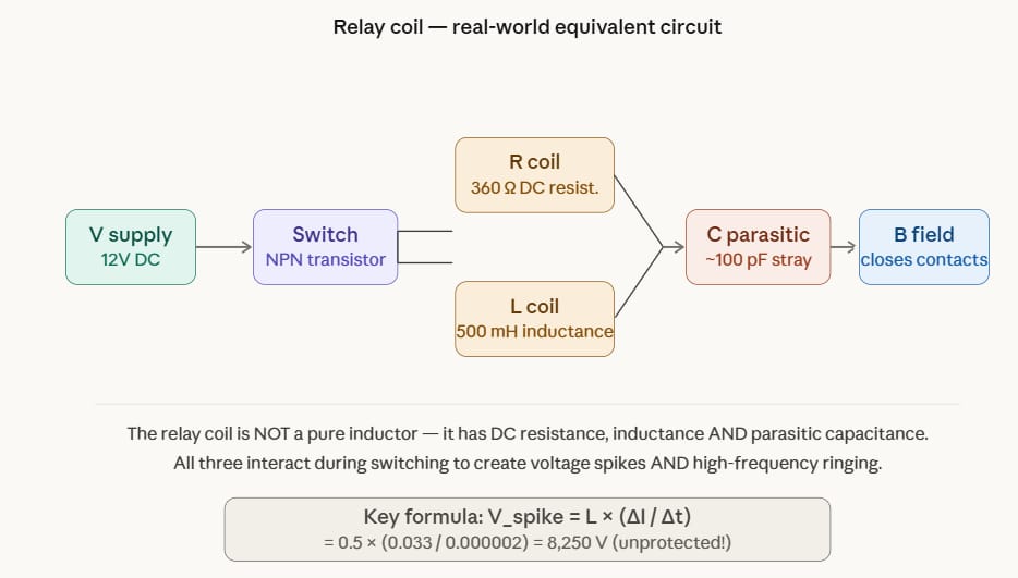
A relay coil is not just an inductor. It has three real electrical properties working together: DC resistance (R), inductance (L), and parasitic capacitance (Cp). When the transistor turns OFF, the stored magnetic energy has nowhere to go and it tries to keep current flowing by spiking the voltage to destructive levels.
The math is brutal: For a standard 12V relay (L = 500 mH, I = 33 mA, turn-off in 2 µs):
V_spike = L × (ΔI/Δt) = 0.5 × (0.033/0.000002) = 8,250 Volts
A 12V circuit generates 8,250V. Without protection, your transistor is dead in nanoseconds.
The Flyback Diode — First Line of Defense
Now let's look at exactly where the flyback diode sits in the circuit and what it actually does.
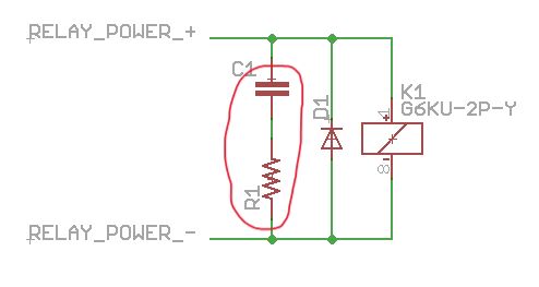
This diagram shows the critical insight: the flyback diode and coil-side snubber live on the left side (driver circuit), while the contact-side snubber lives on the right side (load circuit). These are two electrically separate circuits. Whatever happens on the right side is completely invisible to the flyback diode.
Voltage Waveforms — What Actually Happens in Each Scenario
This is where things get visually very clear. Let's look at the actual voltage waveform at the transistor collector in five different scenarios.
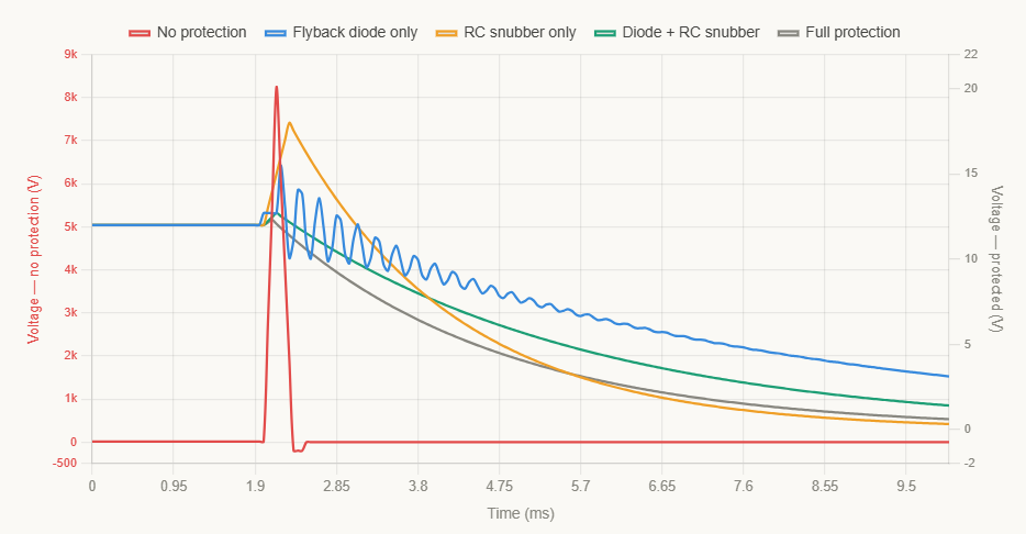
Notice how the flyback diode does a brilliant job clamping the spike but the ringing that remains is the RC snubber's job to kill. Only the combination gives you a perfectly clean waveform
The Three Problems a Flyback Diode Cannot Fix
Here are the three real problems that exist beyond the transistor's collector pin all invisible to the flyback diode:
Problem 1 — Slow relay release time. The flyback diode creates a slow current decay path through the coil resistance. The release time stretches to 5τ = 5 × (L/R) = 5 × (0.5/360) = 6.9 ms. In precision timing or safety-critical systems, this is unacceptable.
Problem 2 — Contact arcing on the load side. When contacts open while switching an inductive load (motor, solenoid), a destructive arc forms. The flyback diode is on the coil circuit it has zero jurisdiction over the contact circuit.
Problem 3 — High-frequency EMI ringing. The parasitic LC network (L = 500 mH, Cp = 100 pF) rings at:
f_ring = 1 / (2π × √(L × Cp)) = 1 / (2π × √(0.5 × 100×10⁻¹²)) ≈ 22.5 kHz
This 22.5 kHz ring corrupts ADC readings, resets microcontrollers, and fails EMC certification tests.
EMI Ringing — Why This Kills Your Electronics
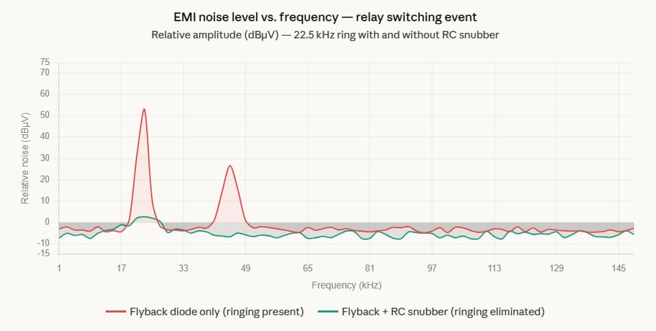
The peak at 22.5 kHz is the relay's natural LC ringing frequency. Without the RC snubber, this spike radiates through your PCB traces, coupling into sensor lines, ADC inputs, and audio circuits. With the snubber, the entire spectrum flattens out to the noise floor.
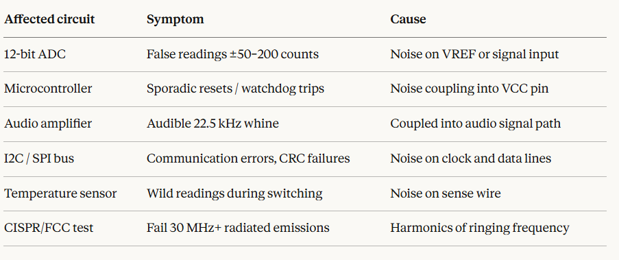
Here is what that ringing actually damages in real circuits:
Affected circuitSymptomCause12-bit ADCFalse readings ±50–200 countsNoise on VREF or signal inputMicrocontrollerSporadic resets / watchdog tripsNoise coupling into VCC pinAudio amplifierAudible 22.5 kHz whineCoupled into audio signal pathI2C / SPI busCommunication errors, CRC failuresNoise on clock and data linesTemperature sensorWild readings during switchingNoise on sense wireCISPR/FCC testFail 30 MHz+ radiated emissionsHarmonics of ringing frequency.
Release Time Comparison — The Speed Trade-off
One more important chart: how quickly does the relay actually release under different protection schemes? This matters hugely in timing-critical applications.
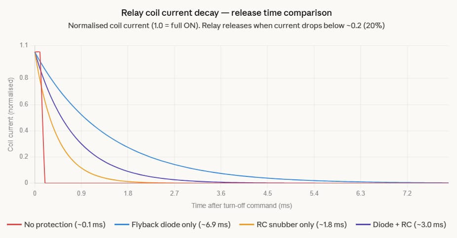
The flyback diode alone creates the slowest release — 6.9 ms — because it provides the lowest-resistance path for current recirculation, letting energy bleed away slowly through the coil resistance. The RC snubber provides a lower-impedance absorption path that speeds things up significantly while still protecting everything.


