

Last updated: 2026
Reverse polarity - connecting the positive power supply to the ground and vice versa , is one of the most common causes of catastrophic hardware failure.
Whether you are designing a hobbyist project, a battery-powered wearable, or an industrial automation system, building robust protection into your power input stage is non-negotiable.
In this comprehensive guide, we break down the five most popular topologies, analyze them with real-world technical data, and establish a clear framework for when to select each.
1. The Series Diode Protection
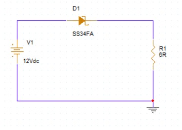
The simplest and most classic approach to keeping your circuit safe is placing a standard rectifier or Schottky diode directly in series with the positive power rail.
How It Works
When the power supply is connected correctly, the diode is forward-biased, allowing current to flow into the load. If the supply is reversed, the diode becomes reverse-biased, acting as an open switch and completely blocking the harmful negative voltage from reaching your downstream components.
Design Challenge:Voltage Drop and Power Dissipation
While incredibly simple, the major downside is the diode's forward voltage drop (Vf).
-
Standard Silicon Diode: Vf ≈ 0.7 V to 1.1 V
-
Schottky Diode: Vf ≈ 0.3 V to 0.5 V
Real-World Numerical Example
Let's look at how this impacts a design under a typical load:
-
Input Voltage (Vin): 12 V
-
Load Current (ILoad): 2 A
-
Voltage Delivered to Load = Vin - Vf= 12 V - 0.5 V = 11.5 V
-
Power Wasted as Heat (PD) = ILoad × Vf = 2 A × 0.5 V = 1.0 W
When to Prefer This Circuit
-
Ultra-Low Current Applications: Best for devices drawing less than 100 mA to 300 mA (e.g., small sensor nodes, low-power microcontrollers) where power loss is negligible.
-
Extreme Bill of Materials (BOM) Cost Constraints:When every fraction of a cent matters, a single diode is the cheapest protection available.
-
High Input Voltages with Wide Tolerances: If your downstream regulator can easily handle a minor voltage drop (e.g., dropping from 24 V to 23.5 V before entering a buck converter).
2. Shunt (Crowbar) Diode with Fuse
If you absolutely cannot tolerate a voltage drop across your power rail during normal operation, the Shunt (or Crowbar) method steps up to the plate.
How It Works
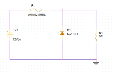
In this configuration, a diode is placed in parallel (shunt) with the load, pointing backward relative to normal power flow. A fast-acting fuse is placed upstream in series with the input.
Normal Operation: The diode is reverse-biased and draws practically zero current. The load receives the full input voltage.
Reverse Event: The diode becomes forward-biased, creating an intentional, dead-short circuit across the power lines. This forces a massive spike in current, which immediately blows the fuse and disconnects the circuit.
Real-World Numerical Example
-
System Settings: 5 V system drawing 1 A normal current.
-
Fuse Selected: 1.5 A Fast-Acting Fuse.
-
Diode Selected: 1N5401 (3 A continuous rating, capable of handling high transient peak currents).
-
Reverse Event: The power supply is hooked up backward. The 1N5401 clamps the reverse voltage to roughly -0.8 V (protecting the load from getting a destructive -5 V), while pulling over 5 A from the source. Within milliseconds, the fuse melts, opening the circuit safely.
When to Prefer This Circuit
-
Zero Normal-Operation Voltage Drop Required: Essential for systems where the input voltage is tightly matched to the load requirements (e.g., a regulated 5 V USB input where a diode drop would break logic thresholds).
-
User-Serviceable Devices: Prefer this when the device is designed for industrial or consumer environments where an end-user can easily swap out a blown fuse.
-
High Transient Voltage Protection: Double-safeguards the system because the shunt diode can also act as a transient voltage suppressor (TVS) against brief spikes.
3. P-Channel MOSFET (High-Side Protection)
To completely eliminate both the voltage drop of a series diode and the destructive nature of a blown fuse, engineers turn to MOSFETs.
How It Works
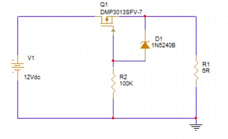
A P-Channel MOSFET (PMOS) is placed on the High-Side (positive rail). The MOSFET is installed "backward" so that its internal body diode conducts during initial power-up.
Once the body diode conducts, the voltage at the source pin rises, and because the gate is tied to ground, VGS becomes highly negative.
This turns the PMOS fully ON. The current then bypasses the body diode completely, flowing through the ultra-low resistance channel (R_DS(on)).
Real-World Numerical Example
-
Input Voltage (Vin): 12 V
-
Load Current (ILOAD): 4 A
-
PMOS Chosen: AO4407A (R_DS(on) = 14 mΩ or 0.014 Ω)
-
Voltage Drop = ILOAD × R_DS(on) = 4 A × 0.014 Ω = 0.056 V
-
Power Dissipation = ILOAD² × R_DS(on) = (4 A)² × 0.014 Ω = 0.224 W
Compared to the 1 W or 2 W loss of a standard diode, a PMOS drops less than 60 mV and stays completely cool.
When to Prefer This Circuit
-
Battery-Powered Devices: Essential for smartphones, wearables, or laptops where conserving milliwatts extends battery life drastically.
-
Unattended or Sealed Consumer Electronics: Perfect when a fuse swap is impossible because the device is permanently sealed or glued shut. The circuit resets automatically once the correct polarity is restored.
-
Standard High-Current Rails (1 A - 5 A): Ideal for general embedded systems running off standard DC adapters.
4. N-Channel MOSFET (Low-Side Protection)
NMOS transistors are generally cheaper and possess significantly lower internal resistance (R_DS(on)) than their PMOS counterparts of the same package size.
How It Works
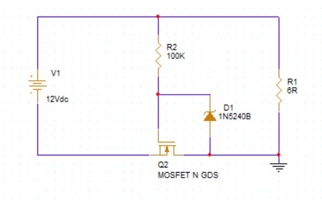
The NMOS is placed on the Low-Side (ground return path). Similar to the PMOS circuit, it utilizes the internal body diode to kickstart conduction
which then biases the Gate positive relative to the Source, turning the NMOS fully ON.
Real-World Numerical Example
-
Input Voltage (Vin): 12 V
-
Load Current (ILOAD): 10 A (High-power application)
-
NMOS Chosen: IRFZ44N (R_DS(on) = 17.5 mΩ)
-
Voltage Drop on Ground Rail = 10 A × 0.0175 Ω = 0.175 V
-
Power Dissipation = (10 A)² × 0.0175 Ω = 1.75 W
The Critical Catch (Ground Floating): While efficient, the NMOS topology introduces a small resistance into the ground path.
This means your system's internal ground is slightly higher than the actual power supply ground.
If your device communicates with external equipment that shares the original power supply ground, you create a ground loop that can cause communication errors or short circuits.
When to Prefer This Circuit
-
Isolated, Standalone Systems: Best for self-contained, high-power systems that do not connect external data cables (e.g., standalone battery packs, power tools, localized LED driver matrices, or isolated RC vehicles).
-
Extreme High-Current / Low-Cost Projects: When handling massive currents (>10 A) on a tight budget where an equivalent PMOS would be too bulky or expensive
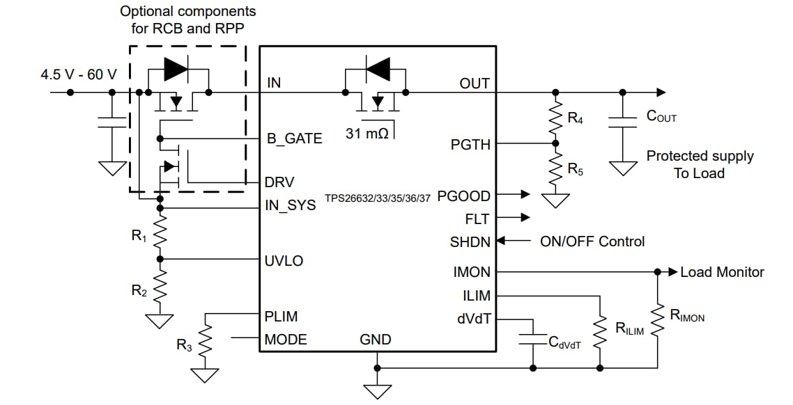
5. EFuse + External MOSFET (Active Ideal Diode)
When you are designing mission-critical hardware, automotive systems, or enterprise servers, you need absolute control and speed.
How It Works
An eFuse or smart controller actively monitors the voltage differential between the input and the output. If a reverse polarity or reverse current event occurs
an internal high-speed comparator detects it within microseconds and drives the gate of an external N-channel MOSFET low, cutting off the circuit before a negative surge can propagate downstream.
Real-World Numerical Example
-
Input Voltage (Vin): 24 V industrial rail
-
Load Current (ILOAD): 5 A
-
Controller Used: Texas Instruments LM74700-Q1 Smart Diode Controller
-
Response Time: Shutoff happens in less than 0.75 μs (microseconds).
When to Prefer This Circuit
-
Automotive Systems (12V/24V/48V): Crucial for car electronics that experience harsh severe voltage fluctuations ("load dumps") or accidental reverse battery jumps.
-
Industrial Automation & Servers: Best for hot-swappable equipment, telecom racks, and industrial PLC modules where uptime is paramount.
-
All-In-One Protection Needs: When you need reverse polarity protection integrated smoothly alongside over-voltage, under-voltage, and short-circuit current-limiting features in a single stage.
6. Summary Table
.png)