
Last updated: 2026
What serial communication really is : Before we compare the three, let us be clear about what they have in common. All three are serial protocols. They send data one bit at a time, in single file, down a small number of wires.
Parallel vs serial: why we mostly gave up on parallel
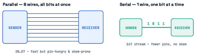
The obvious way to move a byte is parallel: use eight wires and send all eight bits at once. It sounds faster, and for a single clock tick it is. But parallel has ugly problems that get worse as speed climbs:
-
Pin cost. Eight data lines eat eight MCU pins. Add control lines and you are spending a dozen pins to talk to one chip.
-
Skew. At high speed, the eight bits do not all arrive at the same instant. Tiny differences in trace length make them slide out of alignment, and the receiver reads garbage.
-
Cost and space. More wires means wider ribbon cables, more PCB routing, more connectors, more money. Serial trades width for simplicity. Fewer wires, no skew between data lines, cheaper cables, easier routing. You pay by sending bits in sequence instead of all at once but modern serial buses run fast enough that this rarely matters. That is why almost everything on a modern board, from SATA to USB to PCIe to our three little buses, is serial.
Where these three fit
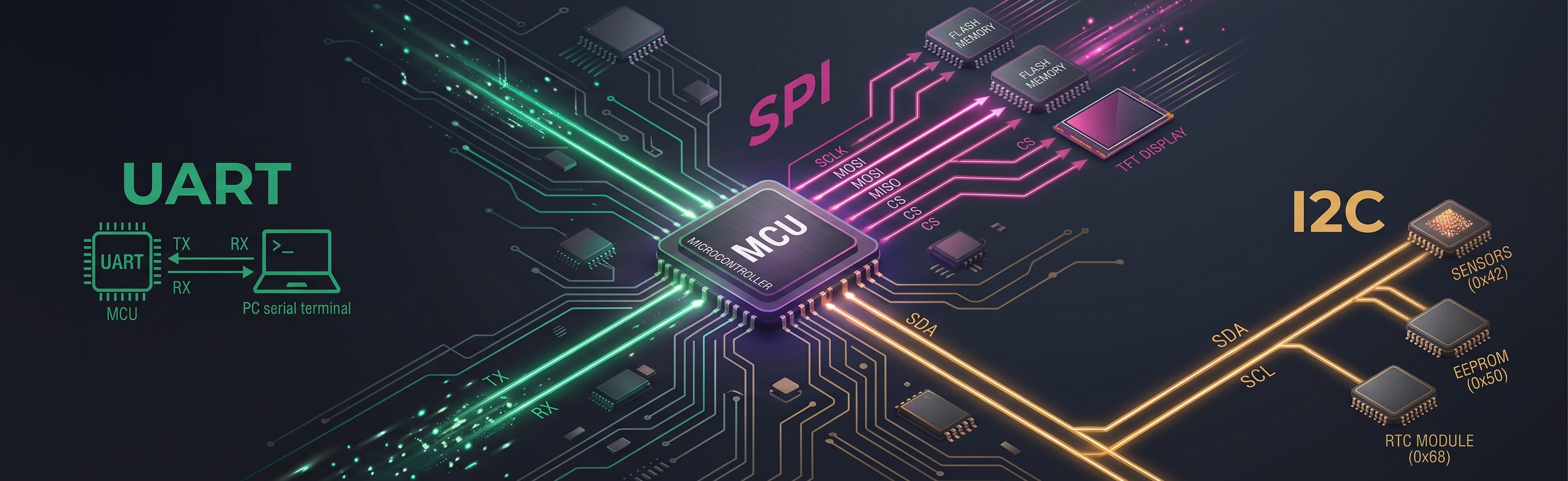
UART, SPI, and I2C are all short-haul, on-board (or short-cable) serial links used to connect a microcontroller to its neighbours - sensors, memory, displays, radios. They are not networking protocols like Ethernet or CAN; they are the everyday plumbing between a processor and the chips sitting next to it. Understanding their differences is one of the most practical skills in embedded design, and one of the most common topics in hardware interviews.
1.Understanding UART (The point-to-point talker)
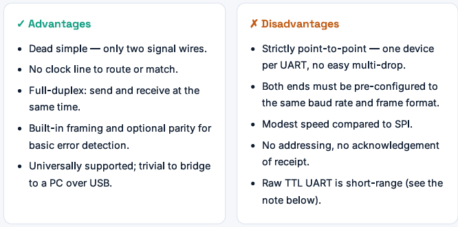
UART stands for Universal Asynchronous Receiver / Transmitter. Strictly speaking it is not even a "bus" and not really a protocol in the same sense as the others - it is a hardware block inside your MCU that turns bytes into a bit stream and back. But everyone treats "UART" as shorthand for the simple two-wire serial link it produces, so we will too.
How UART works
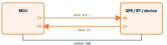
UART connects exactly two devices, one to one. Each device has a TX (transmit) pin and an RX (receive) pin. You wire them in a cross: one device's TX goes to the other's RX, and vice versa. Add a common ground and that is the whole connection
TX → RX and RX ← TX. Wiring TX to TX is the classic first-day mistake.
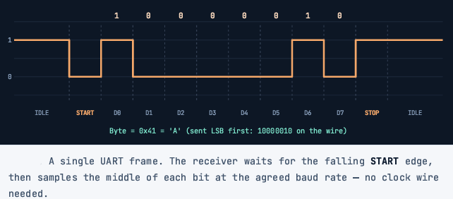
The "asynchronous" part is the clever bit. There is no clock wire. Instead, both sides agree in advance on the speed the baud rate and each side times the bits with its own internal clock. A byte is wrapped in framing so the receiver can find it in the stream:
Idle line sits HIGH.
- Start bit — the line drops LOW for one bit. This falling edge tells the receiver "a byte is coming, start your timer."
- Data bits — usually 8, sent least-significant-bit first.
- Parity bit (optional) — a simple error check.
- Stop bit(s) — the line returns HIGH for one or two bits, marking the end
DEBUG REALITY
-
UART bits are read LSB-first, so the waveform looks "backwards" from the hex value. Byte 0x41 shows on the wire as 1 0 0 0 0 0 1 0. Many hours have been lost by engineers reading a logic-analyzer trace MSB-first and concluding their firmware is broken.
-
Baud rate: the one number both sides must share
Baud rate is bits per second on the wire — 9600, 57600, 115200, and so on. Because there is no shared clock, if the two ends disagree on baud rate, the receiver samples at the wrong moments and you get corrupted bytes. Most UART controllers tolerate roughly a ±2–3% mismatch before framing errors appear; beyond that, data turns to mush. This is why a "garbage on the terminal" bug is almost always a baud-rate or clock-configuration problem, not a wiring one.
Where you actually find UART
GPS modules stream NMEA sentences over UART. Debug consoles (that printf you rely on) are UART. Classic Bluetooth and cellular modules take AT commands over UART. Industrial equipment uses UART-over-RS-485 for Modbus RTU across a factory floor.
2.Understanding I2C (The crowd manager)
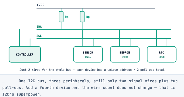
I2C (Inter-Integrated Circuit, pronounced "eye-squared-see" or "eye-two-see"), invented by Philips now NXP solves a different problem: how do you connect a dozen chips using as few pins as possible? The answer is a shared two-wire bus where every device has an address.
Two wires, many devices
I2C uses just two lines, shared by everyone on the bus:
-
SDA — Serial Data (bidirectional).
-
SCL — Serial Clock (driven by the controller).
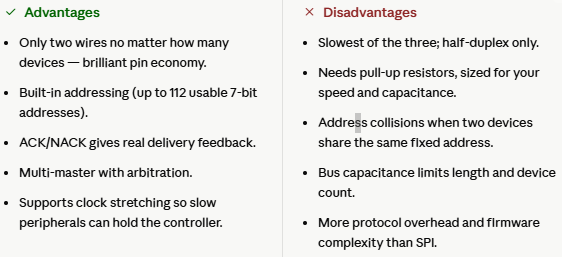
Both lines are open-drain. That means a device can only pull a line LOW; it can never drive it HIGH. To return the line to HIGH you need external pull-up resistors. This open-drain design is what lets many devices share the same wires without ever fighting each other electrically and it is also why forgetting the pull-ups is the number-one I2C failure
Addressing, ACK, and Multi-master
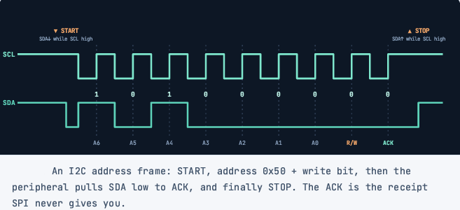
Since everyone shares the wires, I2C needs a way to say "I'm talking to you." Each transaction begins with the controller sending a 7-bit address (10-bit addressing also exists) followed by a read/write bit. Only the device with that address responds; the rest ignore the traffic. After each byte, the receiver pulls SDA low for one clock to send an ACK (acknowledge). No ACK — a NACK — means "nobody home" or "I'm done." This handshake is genuinely useful: an I2C bus scan works by sending every address and watching for an ACK. I2C also supports multi-master operation, with built-in arbitration if two controllers start talking at once. Two conditions frame everything, and they are what make I2C instantly recognizable on a scope:
-
START: SDA falls while SCL is HIGH.
-
STOP: SDA rises while SCL is HIGH.
During normal data, SDA is only allowed to change while SCL is LOW. So any SDA transition during a HIGH clock is, by definition, a START or STOP.
Speed modes
I2C is the slowest of the three by design, but it has grown faster over the years: Standard 100 kHz, Fast 400 kHz, Fast Mode Plus 1 MHz, and High-Speed 3.4 MHz. Most everyday sensors run at 100 or 400 kHz. Push the clock faster and your pull-up sizing and bus capacitance become critical.
Practical starting points: 4.7 kΩ at 100 kHz, 2.2 kΩ at 400 kHz, ~1 kΩ at 1 MHz. More devices or longer traces raise Cb, so lower the resistor to keep edges sharp.
Where you actually find I2C
EEPROMs for config storage. Small sensors temperature, humidity, pressure, IMUs, ambient light. RTC modules (real-time clocks like the DS3231). PMICs and power management chips. Basically anything low-speed where board space and pin count matter more than throughput.
3.Understanding SPI (The speed demon)
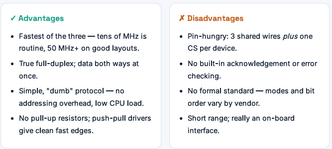
SPI is the Serial Peripheral Interface. When you need raw throughput pushing pixels to a display, streaming samples from a fast ADC, reading a flash chip SPI is almost always the answer. It buys that speed by using more wires and a dedicated clock.
The four wires
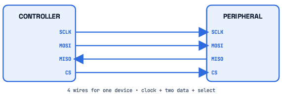
SPI is synchronous: the controller generates a clock, so both sides always agree on timing. It is also full-duplex — data flows both directions at once on separate lines.
-
SCLK — serial clock, driven by the controller.
-
MOSI — Controller Out, Peripheral In (data from controller to peripheral).
-
MISO — Controller In, Peripheral Out (data back the other way).
-
CS / SS — Chip Select (active LOW). Pulling it low activates one peripheral.
Adding more devices: one CS per peripheral
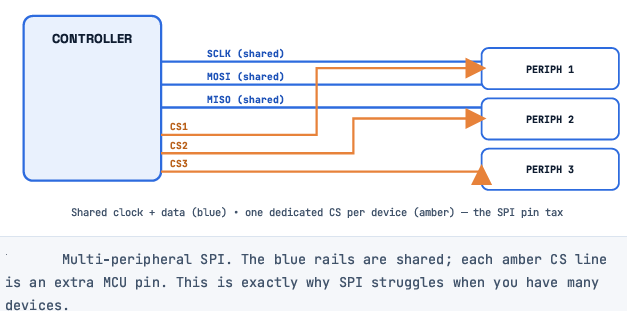
Here is SPI's scaling story. SCLK, MOSI, and MISO are shared across all peripherals. What is not shared is Chip Select: every peripheral needs its own CS line. Three peripherals, three CS pins. Ten peripherals, ten CS pins. This is SPI's tax — pin count grows one-for-one with device count.
The SPI waveform
.png)
THE FOUR SPI MODES TRAP
SPI has four modes set by two bits — CPOL (clock idle level) and CPHA (which edge samples data): Mode 0 (0,0), Mode 1 (0,1), Mode 2 (1,0), Mode 3 (1,1). If your controller and peripheral disagree on the mode, you get data that is bit-shifted or complete nonsense. Always check the peripheral datasheet's timing diagram and match it exactly. This is the single most common SPI bring-up bug.
CRITERION |
UART |
I2C |
SPI |
SIGNAL WIRES |
2 (TX, RX) + GND |
2 (SDA, SCL) + GND |
4: SCLK, MOSI, MISO + 1 CS per device |
TYPICAL SPEED |
9.6 kbps – ~1 Mbps |
100 kHz / 400 kHz / 1 / 3.4 MHz |
10 – 60+ MHz (fastest) |
CLOCK |
None (asynchronous) |
Shared SCL (synchronous) |
Dedicated SCLK (synchronous) |
DUPLEX |
Full-duplex |
Half-duplex |
Full-duplex |
ADDRESSING |
None (point-to point) |
Hardware select (CS line) |
7- or 10-bit software address |
MULTI-DEVICE |
No (1:1 only) |
Yes — same 2 wires |
Yes — +1 CS pin each |
ERROR HANDLING |
Optional parity bit |
ACK / NACK per byte |
None built in |
DISTANCE |
Short (TTL); long via RS-485 |
Short; extendable with buffers |
Short (on-board) |
NOISE IMMUNITY |
Moderate (high w/ RS-485)Moderate (high w/ RS-485) |
Low (capacitance sensitive) |
Low–moderate |
5.Conclusion & Key Takeaways
Selecting the right communication protocol does not require over-engineering. It comes down to identifying the core constraints of your physical system design:
-
Choose UART if you need a simple, direct point-to-point link over moderate distances with minimal wire counts, such as external modules or PC debug consoles.
-
Choose SPI when raw data speed is your absolute priority, such as writing to fast memory chips, rendering graphics on displays, or reading high-frequency ADCs.
-
Choose I2C when you need to network a large array of low-to-medium-speed sensors and peripherals while preserving precious microcontroller pins and routing space.